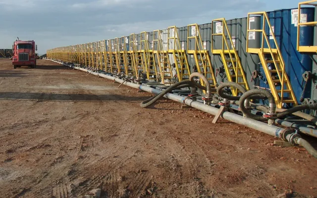
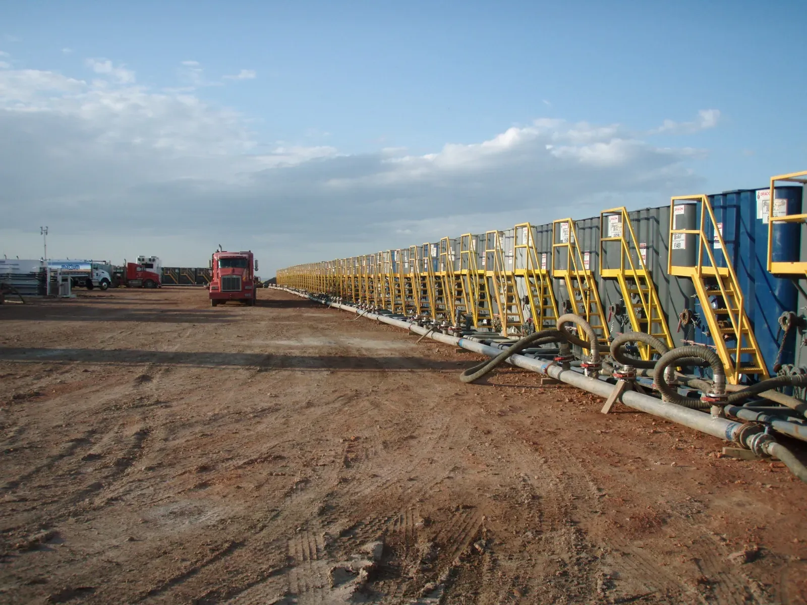
Frac tank secondary containment comes down to three questions: what’s in the tanks, whether they’re tied together, and how much rain the berm has to hold on top of a spill. A 500-barrel frac tank holds 21,000 gallons, so even a single tank needs a serious berm. Put six of them in a row with a manifold across the front and the layout decisions start to matter as much as the berm itself.
This guide walks through which federal rule covers frac tanks on your location, the common layout options, a worked sizing example for a six-tank row, and the spots around the manifold and hoses where small leaks actually happen.
Does a frac tank need secondary containment?
It depends first on the fluid. The federal SPCC rule (40 CFR Part 112) covers oil, including crude, condensate, diesel and oily produced water. A frac tank holding fresh water isn’t an SPCC container. One holding flowback with oil on it, produced water with free-phase oil, or diesel almost certainly is, provided the facility meets the rule’s thresholds and a discharge could reach navigable waters. The existing guide on whether your site needs secondary containment covers that applicability test.
Then it depends on what kind of facility the tanks are sitting on, because Part 112 has different sections for different operations:
| Where the frac tank sits | SPCC section | What it asks for |
|---|---|---|
| Drilling or workover location (including the completion phase) | 112.10(c) | Catchment basins or diversion structures to contain fuel, crude or oily drilling fluids. EPA says this has no specific sizing or freeboard requirement and works like the general rule |
| Onshore production facility (tank battery, separation, treating) | 112.9(c)(2) | Containment for the entire capacity of the largest single container plus sufficient freeboard for precipitation |
| Other onshore facility (yard, terminal, staging area) | 112.8(c)(11) for mobile/portable containers | Largest single compartment or container plus sufficient freeboard for precipitation |
| Everywhere above | 112.7(c) general | Containment for the typical failure mode and most likely quantity, for piping, transfer areas and similar |
Two cautions. First, your SPCC Plan decides how your facility is classified, so check it before you assume the lighter drilling-site rule applies. Second, Texas Railroad Commission rules apply on top of the federal ones in the Permian, so treat the federal minimum as a floor.
The manifold trap: what “largest single container” means
Most sizing mistakes on frac tank rows come from one detail in EPA’s guidance. When tanks are permanently manifolded so they work as one storage unit, EPA says “the total capacity of manifolded containers is the design capacity standard” for sized containment.
Six 500-barrel tanks tied together with open valves aren’t six 21,000-gallon containers. They’re one 126,000-gallon container. A berm sized for one tank won’t hold a failure that drains the whole set through the manifold.
There are two ways to deal with this:
- Isolate the tanks. Keep valves between tanks closed except during transfers, and document that in the Plan. Then the largest single container is one tank.
- Size for the combined volume. This usually means a high-wall system or a much larger footprint, which is often impractical on a crowded pad.
Talk to the engineer who certifies your Plan about which approach the site uses before ordering the berm.
Layout options for a row of frac tanks
| Layout | Good for | Watch out for |
|---|---|---|
| One shared berm under the whole row | Tanks set tight together; one liner to inspect | Every other tank in the berm displaces volume; one puncture drains the whole system |
| Individual berm per tank | Tanks with different fluids, or tanks that come and go at different times | Gaps between berms where the manifold and hoses sit uncontained; more walls to cross |
| High-wall containment | Limited footprint, sloped pads, or manifolded tanks counted as one container | Taller walls need proper support; access for hoses and personnel |
On most Permian pads where tanks sit side by side for a few weeks, a shared berm with the manifold inside it is the simplest setup to install and inspect. That works as long as the volume math holds up once displacement and rain are counted.
Worked example: sizing a shared berm for six frac tanks
These numbers are an example only. Use the dimensions on your own tanks’ spec sheets and the rainfall figure your Plan uses.
Assumptions: six 500-barrel tanks, not manifolded (valves closed), each with a footprint of about 8.5 ft by 46 ft. Tanks set 2 ft apart with a 5 ft buffer inside the berm wall on every side.
- Berm footprint. Width: (6 × 8.5) + (5 × 2) + (2 × 5) = 71 ft. Length: 46 + 10 = 56 ft. Area: 71 × 56 = 3,976 ft².
- Largest single container. 500 bbl × 42 = 21,000 gal ÷ 7.48 = about 2,807 ft³.
- Displacement. The five tanks that didn’t fail still sit in the berm and take up space below the wall top. Their footprint is 5 × (8.5 × 46) = 1,955 ft². That leaves 3,976 − 1,955 = 2,021 ft² of effective floor area.
- Rain. NOAA Atlas 14 gives about 5.0 inches for the 25-year, 24-hour storm at Midland International Airport. EPA’s guidance describes that storm as a reasonable basis for freeboard, while noting the rule leaves the method to good engineering practice. Rain falls on the whole berm: 3,976 ft² × (5 ÷ 12) ft = about 1,657 ft³.
- Required wall height. (2,807 + 1,657) ÷ 2,021 = about 2.2 ft, or roughly 27 inches.
Without the rain allowance the same berm would need about 17 inches. That’s the gap between a berm that passes on a dry day and one that’s full of rainwater the morning a tank lets go.
For comparison, EPA’s own worked example shows that a “110 percent of the largest tank” rule of thumb can come up short where storms are large. In that example, a dike built to 112 percent held only 1.8 inches of rain.
Note that real frac tanks have rounded or sloped bottoms, sit on skids or axles, and may not displace their full footprint. A detailed calculation will differ. The point of the example is the method: largest container, plus displacement, plus rain.
Don’t forget the manifold and hose drip zones
Sized containment is built around a tank failing, but day-to-day leaks tend to start at the front of the row: the manifold, valves, unions, suction and discharge hoses, and the spot where the vac truck connects. EPA’s guidance lists the typical failure modes at transfer points as a failed hose connection, a bad connection or disconnection, a leaking pump, valve, flange or fitting, and overfilling a container. The SPCC rule’s general requirement in 112.7(c) covers these, sized to the typical failure mode and the most likely quantity.
Practical points for the front of the row:
- Keep the manifold inside the shared berm, not in the gap between the berm and the truck lane.
- Put a drip pan or small mat under each truck connection point.
- Restrain pressurized lines. A hose that whips loose pulls fittings and spills more than it should. See restraint systems.
- Route hoses over the berm wall with a wall protector so the liner isn’t cut where the hose crosses.
Inspecting a frac tank berm during the job
A berm that was right on day one can be wrong by week three. Look at it at every shift change:
- Standing water. Rainwater takes up capacity. Check it for oil before you drain or pump it, and log it.
- Drain valves. Closed and sealed unless someone is actively draining checked rainwater.
- The liner at tank skids, hose crossings and wheel paths, where punctures show up first.
- Wall height. Look for sections pushed down by equipment or vehicles.
- Anything added inside. A pump or a generator parked in the berm is more displacement nobody counted.
Get the layout right before the tanks arrive
Site Safe Solutions designs and installs containment systems for oilfield locations in the Permian Basin. That includes modular drive-over containment, primary pads laid out to the site, and high-wall systems for large volumes or tight, sloped pads. For truck connections and short transfers at the front of the row, Fast Mats give quick drive-over protection. Send the tank count, fluid, pad dimensions and timeline, and the layout can be worked out before the first truck rolls in.