CO2 corrosion, often called sweet corrosion, happens when carbon dioxide dissolves in produced water to form carbonic acid, which then attacks carbon steel tubing. In most basins it’s one corrosion mechanism among several. In the Permian it’s a local fact of life. West Texas has been flooding fields with CO2 for enhanced oil recovery since the early 1970s, so a lot of Permian tubing carries CO2-rich fluid every day. The damage it does is often localized pitting and “mesa” attack rather than even thinning. That’s why it shows up as a hole in one joint long before the string looks worn on average, and why joint-by-joint inspection catches it where averages don’t.
Why the Permian has a CO2 corrosion story
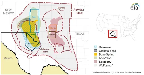
According to a DOE-commissioned NETL study of the basin, CO2 flooding started in the Permian Basin of New Mexico and West Texas in the 1970s. Between 1970 and 1973, Shell and Chevron pioneered tertiary recovery in the area. Chevron built the first supercritical CO2 pipeline to the Kelly-Snyder (SACROC) field, “the first large-scale CO2-EOR project in the Permian Basin.”
By the 1980s, natural CO2 had been found at Bravo Dome, McElmo Dome and Sheep Mountain, and large pipelines were built to carry it to Permian oil fields. The same study, using early-2005 data, counted about 49 active CO2-EOR projects in 35 fields. Together they produced 170,000 barrels a day, almost 20% of the basin’s oil at the time. Wasson, Seminole and Vacuum are among the fields it names.
DOE’s own EOR page says CO2 injection “has been used successfully throughout the Permian Basin of West Texas and eastern New Mexico.” It also says gas injection accounts for nearly 60% of US EOR production.
So in a Permian CO2 flood, the injectors carry CO2 and the producers bring it back with oil and water. Even wells outside a flood can carry CO2 in their produced gas. CO2 corrosion in Permian tubing is a routine operating condition, not a rare one.
How CO2 corrosion works
The chemistry is simple. A 2023 review in iScience summarizes it: CO2 becomes corrosive when it “combines with water to form carbonic acid,” which reacts electrochemically with steel. Dry CO2 isn’t the problem. Water is. The review notes that the corrosion rate of carbon steel “tends to accelerate when the water content in CO2 increases.”
The reaction can lay down an iron carbonate (FeCO3) film. When it’s intact, that film slows further corrosion. When it’s damaged or never forms properly, attack concentrates at the bare spots. According to the review, the factors that drive it include:
- Water content. More water means faster attack.
- Temperature and pressure. Higher values generally make it more corrosive.
- pH. “The higher the pH is, the lower the hydrogen ion content is, and the corrosion rate of carbon steel will also be reduced.”
- H2S. When present, it worsens the damage in combination with CO2.
The review lists the forms of damage as uniform corrosion, pitting corrosion, mesa attack and flow-induced localized corrosion. The last three are local, and local damage is what makes tubing fail early.
Sweet vs sour corrosion
“Sweet” and “sour” are field shorthand. Sweet corrosion is CO2-driven. Sour corrosion involves hydrogen sulfide. Many Permian wells have some of both. This table compares them as corrosion mechanisms in tubing. (H2S is also a serious toxic gas hazard, which is a separate safety subject from this one.)
| Sweet (CO2) corrosion | Sour (H2S) corrosion | |
|---|---|---|
| Driver | CO2 dissolved in water forming carbonic acid | H2S dissolved in water |
| Typical corrosion product | Iron carbonate (FeCO3) film | Iron sulfide films and scale |
| What it looks like in pulled tubing | Pits and patches of localized “mesa” wall loss. Grooving where flow is turbulent | Pitting under sulfide scale. Also cracking risk in susceptible steels |
| Main worry | Localized wall loss leading to a leak | Wall loss, plus cracking of high-strength steel |
| How it’s usually managed | Inhibitors, corrosion-resistant alloys, coatings and liners, water management | Material selection for sour service, plus inhibitors |
| Where it shows up in the Permian | CO2-EOR producers and wells with CO2 in the gas | Wells and floods with H2S in the produced stream |
The iScience review names three main prevention approaches: corrosion inhibitors, coatings and alloy selection. It notes that inhibitors, “owing to their remarkable effectiveness and cost-effectiveness, are currently the primary focus.” In practice an operator’s corrosion program usually combines several. Which ones belong in your wells is a question for your corrosion engineer and your chemical provider.
Why averages hide CO2 damage
Pitting and mesa attack don’t thin a string evenly. One joint can have a pit most of the way through the wall while the joints on either side look new. Those joints can sit in a zone of turbulent flow, at a gas breakout point, or where water accumulates. Average wall loss across the string can look fine while one joint is a few weeks from a leak.
That changes how you inspect:
- Grade every joint, not a sample. A sample of ten joints can miss the one that matters.
- Record where the damage is. If the worst joints cluster at one depth, that points to a flow or water-holdup condition worth fixing, not just pipe to replace.
- Compare pulls. On an EOR producer that gets pulled regularly, compare the location and severity of wall loss from one pull to the next. That shows whether an inhibitor program or a change in operating conditions is working.
- Lay down what won’t make another run. A string with a few badly pitted joints can usually be rerun once those joints are replaced.
Electromagnetic inspection (EMI) of tubing as it comes out of the well detects wall loss, corrosion and other defects joint by joint. For what an EMI scan picks up and how it’s graded, see what EMI tubing inspection finds.
Setting inspection intervals for CO2 wells
There’s no single right interval, but the logic is consistent:
- Start from history. Wells in an active CO2 flood, wells with high water cut, and wells with past tubing leaks get inspected every time the tubing comes out.
- Use pulls you’re already making. Inspecting during a rod job or pump change costs a fraction of a dedicated pull.
- Tighten after a change. A new flood pattern, a change in water cut, or a change in inhibitor program are all reasons to inspect at the next pull, not wait for the next leak.
- Track by joint position. A joint-level record over several pulls is how you learn your own wells’ corrosion pattern.
EMI tubing inspection for Permian wells
Site Safe Solutions provides EMI tubing inspection in the Permian Basin. It uses non-contact electromagnetic methods to detect wall loss, rod wear, corrosion and other defects in tubing, run by experienced operators. If you have CO2-EOR producers or wells with a corrosion history coming out of the hole, tell us the well and the pull date.