Magnetic flux leakage (MFL) is a way of finding missing metal in steel without touching it. The inspection tool magnetizes the tubing wall close to saturation. Wherever corrosion, pitting or wear has thinned the wall, the magnetic field can’t all stay inside the steel. Some of it leaks out into the air, where sensors pick it up. More leakage generally means a bigger defect.
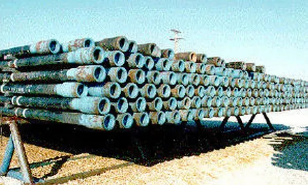
That principle has been used in pipeline “smart pigs” for decades, and most of what you’ll read online is about pipelines. This article applies it to production tubing coming out of a well on a workover, where the question is simpler and more expensive: which joints go back in the hole and which don’t. For what electromagnetic inspection typically turns up in Permian tubing, see what EMI tubing inspection finds. This piece stays on the method.
How magnetic flux leakage works
Think of magnetic flux as flowing through steel the way water flows through a pipe. Iowa State’s NDE education center uses a bar magnet as the example. Crack the magnet and a new north and south pole form at the edges of the crack, so the field spreads out into the air at the flaw. Magnetic particle inspection uses that same leakage, made visible with iron powder.
An MFL tool does the same job electronically:
- Magnetize the wall. Strong magnets push flux along the steel. The PMC review of MFL describes magnetizing the material “close to saturation.” If the wall isn’t magnetized enough, a thin spot can carry all the flux and nothing leaks. If it’s over-magnetized, background noise rises and defects become harder to pick out.
- Let the defect push flux out. Where metal is missing, the magnetic path is harder for the flux to follow, so some of it exits the surface and goes around the defect.
- Measure the leakage. Hall-effect or coil sensors between the magnet poles record the leakage field as the tubing passes. Wikipedia’s MFL article notes that high-resolution pipeline tools measure all three components of that field (axial, radial and circumferential).
- Interpret the trace. An analyst, or software trained on known defects, reads the signal and estimates the size of the metal loss.
For tubing on surface, the tubing moves through or past a ring of magnets and sensors as it’s pulled or racked, rather than a pig travelling inside a buried line. The physics is the same.
What the trace is telling you
An MFL trace is a strip chart along the length of each joint. A clean joint gives a fairly flat signal. Deviations show up as spikes or broader bumps:
- Sharp, short spikes usually mean localized defects such as pits.
- Broader, longer signals usually mean general wall loss over a longer area, the kind of pattern rod wear or general corrosion can leave.
- Bigger signals generally mean more missing metal. The Wikipedia article puts it simply: “the larger the change in the detected magnetic field, the larger the anomaly.”
The trace is a measurement of leakage, not a direct thickness reading. Turning leakage into an estimated depth relies on calibration against known defects. That’s why the inspector’s calibration and experience matter as much as the equipment.
The real value for an operator is joint-level grading. The worst point on a joint, not its average, decides whether it fails downhole. A digital record of each joint also lets you compare the same string the next time it comes out.
What MFL can’t see well
Every method has blind spots. The PMC review lists several for MFL, and they apply to tubing as much as to pipelines:
- Inside versus outside. MFL alone “cannot distinguish between internal and external defects.” Pipeline tools add a separate eddy-current sensor to tell which surface the metal loss is on.
- Narrow axial defects. Long, thin defects running along the pipe axis are harder to detect because they barely disturb flux travelling in the same direction.
- Cracks. Wikipedia notes that a crack’s signature is not easily identified by an MFL tool, and the review notes detection is strongest at and near the surface.
- Speed. The signal is “quite sensitive to the running speed.” Running tubing through too fast or unevenly degrades the data.
- Lift-off. Debris, scale or anything that holds the sensor away from the steel weakens the signal. The review calls lift-off from welds and debris “an insidious problem.”
None of these make MFL a poor choice. They’re reasons to know what was and wasn’t checked, and to clean scale and paraffin off the tubing where it affects the reading.
How MFL compares with other tubing checks
| Method | What it measures | Strengths | Limitations |
|---|---|---|---|
| Magnetic flux leakage (EMI family) | Magnetic leakage caused by missing metal | Non-contact; full-length coverage joint by joint; fast; digital record | Indirect measure of depth; inside/outside ambiguity without an extra sensor; weaker on narrow axial defects and cracks |
| Ultrasonic thickness (UT) | Wall thickness from sound reflection time | Direct thickness reading at the probe | Spot readings unless automated; needs coupling to the surface; slow for a whole string |
| Drift | Whether a mandrel passes through the bore | Simple check for internal obstructions, dents and collapse | Says nothing about wall thickness or pits |
| Visual | Outside surface, threads, obvious damage | Cheap; catches thread and handling damage | Can’t see the inside wall or hidden wall loss |
In practice these are used together. Drift and visual catch damage that magnetic methods aren’t designed to find. MFL finds the hidden wall loss that visual inspection can’t see, and points UT at the spots worth a direct thickness check.
Grading the joints
Inspection results are usually translated into classes, and the joints are marked so the rig crew knows which ones to run. The IADC Lexicon defines the color code as paint-band identification of OCTG classification, citing API RP 5A5, the recommended practice for field inspection of new casing, tubing and plain-end drill pipe. Ask your inspector which classification scheme and wall-loss limits they’re grading to, and make sure it matches what the operator expects.
Questions to ask before a tubing inspection
- What method are you using, and what does it detect and miss?
- How is the equipment calibrated, and against what reference defects?
- What wall-loss thresholds will you grade to, and who set them?
- Will I get a digital record for each joint, tied to its position in the string?
- Does the tubing need cleaning first to get a good reading?
- Can the results be compared with the last inspection of this string?
EMI tubing inspection in the Permian
Site Safe Solutions provides EMI tubing inspection in the Permian Basin. The service uses non-contact electromagnetic scanning to find wall loss, rod wear, corrosion and other defects, down to small diameters, at the wellhead or on the lease, with digital trace records for each job. The company describes itself as the only provider in the Permian Basin with ACE-Making technology. The best time to scan is when the tubing is already out of the hole. Have the tubing size, joint count and timing of the pull ready when you get in touch.