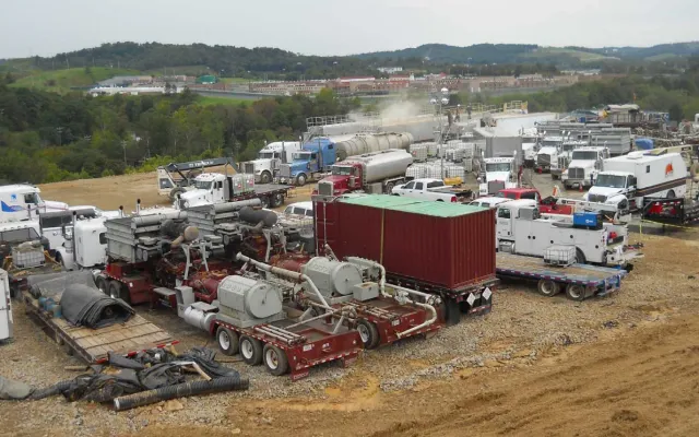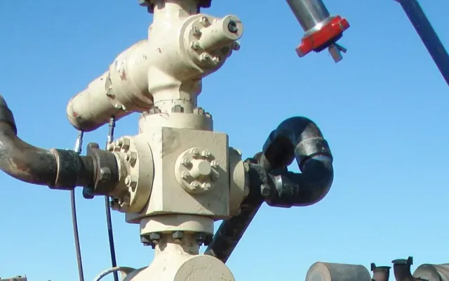
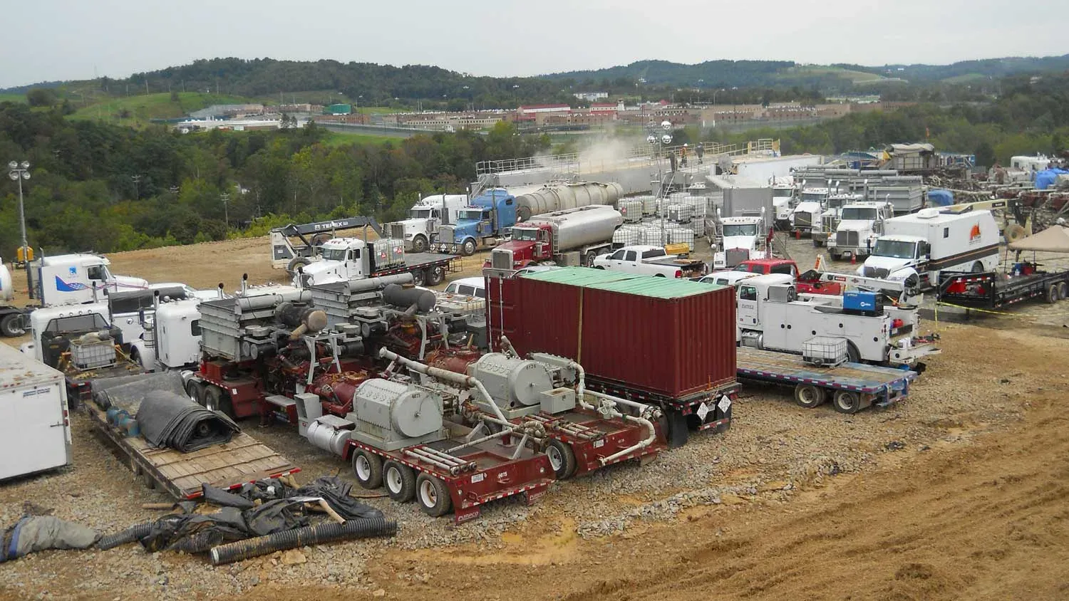
Frac iron is the temporary high-pressure piping, hoses, connections, manifolds and relief devices that carry stimulation fluid from the pumps to the wellhead. Most of the people hurt by it are hurt the same few ways. A union that doesn’t match lets go during the pressure test. A worn connection lets go during the job. A line fails and whips. Frac iron safety comes down to three habits: run only iron you can trace and have inspected, never mix connections that merely look alike, and restrain the lines so a failure stays a failure and doesn’t put someone in the hospital. In January 2026 the industry got its first dedicated standard for it, API Std 16FI.
What API Std 16FI is
On January 20, 2026, the American Petroleum Institute published the first edition of API Standard 16FI, Frac Iron Guidelines and Requirements. According to API’s release, it covers the temporary high-pressure equipment used in hydraulic fracturing: “piping, hoses, connections, manifolds, and pressure-relief devices” that move stimulation fluids to the wellhead. API describes it as guidance “for design, manufacturing, and use” of that equipment, aimed at “safer working conditions and operational integrity at well sites.”
API’s senior vice president of global industry services, Anchal Liddar, put the purpose this way: “Establishing consistent expectations for frac iron equipment is an important step toward enhancing safety across hydraulic fracturing operations.”
That’s what API has said publicly. The full standard is a paid document, and this article doesn’t summarize clauses from it. If your company or your pressure pumper is adopting 16FI, get the document and read the requirements for your role. In practice that means asking your iron provider how their inspection, recertification and tracking program lines up with it.
How frac iron actually hurts people
OSHA’s hazard publication on hydraulic fracturing and flowback names the mechanism directly. Workers can be struck by high-pressure lines, or hit by an unexpected release of pressure, because of “mismatched or excessively worn hammer unions,” line leaks and line failure. It flags two phases in particular:
- Pressure testing before the job. The system is pumped up to test pressure. This is the first time a bad connection sees real load.
- Flowback. Fluid and gas come back through flow lines to tanks or pits, and struck-by hazards from high-pressure lines are present again.
OSHA’s prevention list for those phases is short: fasten high-pressure lines together properly, run adequate pressure tests on pumps and lines, check valve alignment before pumping, keep non-essential people clear, and follow procedures to bleed off trapped pressure safely.
Mismatched unions: the failure that keeps happening
Hammer unions in different figures can look nearly identical and will sometimes thread together. They aren’t rated for the same pressure, and the threads don’t truly match. IADC has published safety alerts on this more than once.
IADC Safety Alert 00-15 describes a 2-inch Fig. 1502 wing nut made up to a Fig. 602 female half from a different service company. During a pressure test it “stripped out and blew off” at 1,300 psi, below the intended 1,500 psi, and struck a third-party employee, “causing serious injury.” In a second incident in the same alert, a 1502 male sub with a pressure sensor “blew off” a 602 female union on a mud pump discharge. Alert 03-16, issued in April 2003, opened with “Reports continue to come in involving pressurized lines and the unions used on these lines.” It also flagged the other habit that goes with it: hammering on lines that are still under pressure.
The fix is boring and it works:
- Match figure number, size and pressure rating on both halves of every union, and check the stamps, not the color.
- Keep different figures physically separated in storage and on the trailer.
- Don’t hammer up a connection that’s under pressure. Bleed it down first.
- Treat any union that “almost” made up as a mismatch until proven otherwise.
For more on the hazard itself, see why an unrestrained line whips.
Managing iron from receiving to retirement
Every iron program that works covers the same life cycle. The specific inspection methods and intervals belong to your iron provider’s program and the applicable standards. This table shows what each stage is for and what to ask.
| Stage | What happens | What to ask your iron provider |
|---|---|---|
| Receiving | Iron is identified (serial or ID), matched to its documentation and rating | Can every piece on location be traced to a record? |
| Pre-job check | Visual check of connections, seals, threads and wing nuts. Figures matched | Who signs off that the rig-up matches the drawing? |
| Rig-up | Lines assembled to a layout, supported, and restrained | Is there a written layout showing restraint points? |
| Pressure test | System tested before the job with people clear | What test pressure and hold time, and who clears the area? |
| In service | Watch for leaks, vibration and movement. No hammering under pressure | What’s the stop-work trigger for a leaking connection? |
| Periodic inspection and recertification | Iron pulled for inspection and testing at intervals or after set use | What method and interval, and what are the reject criteria? |
| Retirement | Iron that fails inspection or reaches its limit is removed and marked | How is retired iron kept from finding its way back to a job? |
If the answers come back vague, the program is probably weak.
Where restraint fits
Inspection and matching reduce how often iron fails. Restraint limits what happens when it does. A properly restrained line that parts at a union stays roughly where it was instead of whipping across the pad. That turns a potentially fatal event into a shutdown and a repair.
What to look for in a restraint setup on frac iron:
- Restraint along the full run, not only at the wellhead
- Anchor points on something that can’t move (a skid that can slide isn’t an anchor)
- Restraint put back on after every line change, not just at the first rig-up
- Hardware that’s quick to refit, so it doesn’t get left off when the crew is under time pressure
- Extra attention where lines cross walkways, work areas and muster routes
None of that replaces matched, inspected iron. Restraint is the backup, and it only works if it’s on the line when the line fails.
Restraint systems from Site Safe Solutions
Site Safe Solutions supplies and installs high-pressure restraint systems for oilfield hoses and iron lines across the Permian Basin, for slick-water, nitrogen, energized fluids and standard pumping work. They use modular hardware packages built to simplify installation and cut downtime during line changes. If you’re planning a rig-up or reviewing how iron is restrained on your locations, send us the application, the pressures and the layout.