A hammer union is the wing-nut connection that ties together most temporary high-pressure lines on location: pump discharge, treating iron, standpipes, test lines. The figure number stamped on it (206, 602, 1002, 1502 and so on) tells you its pressure class. The hazard that has hurt and killed people is a 2-inch mismatch. The wing nut off a 2-inch Figure 1502 will thread onto the threaded half of a 2-inch Figure 602 or 1002, look made up, hold pressure for a while and then blow apart.
That failure is well documented in IADC safety alerts going back to the late 1990s. It still shows up because the parts look close enough on a busy rig floor or frac site. Here is how to read the figure numbers, what the incidents showed, and the check to run before anyone pressures up.
What is a hammer union?
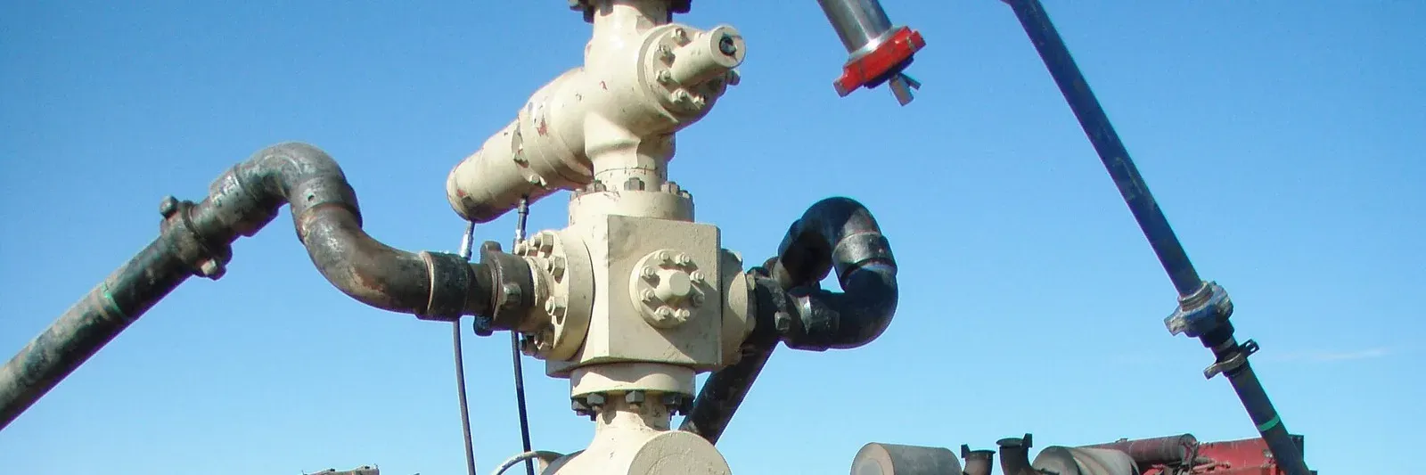
A hammer union has three parts. There is a male sub with a lugged wing nut riding on it, and a female sub with external threads. A seal sits between them. You make it up by threading the wing nut onto the female half and striking the lugs with a hammer until the faces seat. That is quick to rig up and quick to break out, which is why unions are everywhere on temporary iron.
The figure number identifies the design and pressure class. The size is the nominal pipe size. A “2-inch 1502” and a “2-inch 602” are both 2-inch unions, but they are built for very different pressures and they are not meant to mate.
Hammer union figure numbers and pressure ratings
Ratings vary by maker, size and service (standard or sour), so always go by what is stamped on the part and the manufacturer’s literature. As one published example, C&C Flow Control’s chart lists these non-shock cold working pressures (NSCWP) for standard service:
| Figure | NSCWP (psi) | Test (psi) |
|---|---|---|
| 206 | 2,000 | 3,000 |
| 400 | 4,000 | 6,000 |
| 602 | 6,000 | 9,000 |
| 1002 | 10,000 (7,500 in some sizes) | 15,000 (11,250) |
| 1502 | 15,000 | 22,500 |
C&C describes its Figure 602 as suited to manifold and truck mounting and to air, water, oil, gas or mud service up to 6,000 psi, which is why 602s turn up on workover rigs and pump trucks next to 1502 iron.
Two things in that table catch people out. First, a “1002” is not always a 10,000 psi union, because the rating depends on size. Second, colour is a poor guide. Manufacturers use their own paint schemes. C&C’s Figure 602, for example, ships with orange subs and a black nut. Read the stamp, not the paint.
Why does a 1502 thread onto a 602?
IADC Safety Alert 03-16 explains the mechanics. On 2-inch unions, the threaded half of a Figure 602 or 1002 and the wing nut of a Figure 1502 have threads of the same pitch and design, so they screw together. But there is a 5/16-inch difference between the diameters of the two halves. The connection looks made up and the crew believes it is good for the 1502 rating. In reality it will not hold high pressure for long, and the halves eventually separate.
The alert lists three hazards created the moment the halves blow apart:
- The wing nut becomes a projectile of about 8 pounds, travelling in any direction.
- High-pressure fluid releases without control and can strike anyone in its path.
- Potentially toxic fluids (acid, oil, fuel, diesel-based mud) are released.
The same alert reports several industry accidents, including a fatality, from lines that were improperly connected or hammered on while under pressure.
What the IADC incidents showed
Alert 00-15 describes two 2-inch mismatches. In the first, a 1502 wing nut and male sub carrying a pressure sensor were attached to a 602 female half on a mud pump. The union and sensor blew off the pump discharge. In the second, one service company’s 1502 wing nut was made up to another service company’s 602 female half. The crew was testing surface casing with a planned test pressure of 1,500 psi. At 1,300 psi the 1502 stripped out, blew off and seriously injured a third-party service hand.
Note the numbers. The connection failed below the test pressure, far below what anyone would expect from a 1502. That fits the alert’s description of the cause: mismatched halves “appear to be tight, and hold pressure for a time” until they reach the give point.
The second incident also shows where mismatches come from. They usually happen at the interface between two companies’ equipment, where each crew assumes the other side matches.
Alert 99-33 records an industry meeting in Houston in November 1999 that concluded “a quick and universal engineering solution appears elusive.” It listed the controls still in use today: colour coding of high-pressure piping and end connections, pipe management systems that trace testing and end connections, go/no-go ring gauges to verify thread-half size, and swapping to 3-inch unions at connection points. It also raised a less obvious risk. If 1502s replace 602s on a low-pressure line, supervisors might be tempted to pressure the whole line up to 1502 ratings.
What has API done about mismatched unions?
API’s answer has come in stages:
- API RP 7HU1, Safe Use of 2-inch Hammer Unions for Oilfield Applications. A recommended practice aimed at the 2-inch mismatch problem.
- API Spec 7HU2, Oilfield Hammer Unions (first edition released March 2022). API’s release describes it as a manufacturing standard that builds on RP 7HU1 and targets the incompatibility that “has led to mismatching field incidents.”
- API Std 16FI, Frac Iron Guidelines and Requirements (released January 20, 2026). API’s public release says this first-edition standard covers the design, manufacturing and use of frac iron, meaning the temporary high-pressure piping, hoses, connections, manifolds and pressure-relief devices used during hydraulic fracturing.
Standards only help if the iron on location was built and is managed to them. Older inventory and mixed fleets are still out there. Field controls still matter.
A pre-pressure-up connection checklist
Most of this comes straight from the corrective actions in IADC alerts 99-33, 00-15 and 03-16, and from manufacturers’ published warnings:
- Read the stamp on both halves. Same figure, same size, same service class (standard or sour). C&C’s literature warns never to mix components with different pressure ratings and never to interchange sour-service and standard-service parts.
- Check every interface between companies. Rig to service company, pump truck to manifold, third-party test equipment. IADC 00-15 calls for inspecting service companies’ 2-inch unions before they connect to the rig or to each other.
- Gauge it when in doubt. Go/no-go ring gauges exist to verify thread-half size.
- Limit union types on location. One company in IADC 03-16 standardised on Figure 1502 for 2-inch connections on its drilling rigs and required supervisors to inspect service company connections on workover rigs that used 602s.
- Mark connection points. IADC 00-15 suggests “Danger” signs at rig connection points stating which 2-inch union type is in use.
- Bleed off before you break. Confirm pressure is bled off before breaking a line, and use lockout/tagout and permits on pressurised lines. Never hammer a union under pressure.
- Retire damaged parts. Manufacturers warn against using worn, eroded or corroded components and against striking unions with deformed or flattened lugs.
- Put it in the JSA. Talk through how to tell 1502, 1002 and 602 apart in JSAs and safety meetings for any job that makes up 2-inch unions.
Why restraints still matter when the unions are right
Every control above aims to stop a connection from letting go. None of them can promise it won’t. Unions also fail from erosion, fatigue and damaged lugs. When a connection on high-pressure iron or hose does part, the line wants to move, and the wing nut becomes a projectile. Our guide to the high-pressure line whip hazard explains the mechanics.
Restraints don’t prevent the failure. They hold the iron or hose near where it was so the release stays a shutdown and a repair instead of a struck-by.
Restraining the iron on your location
Site Safe Solutions provides hose restraints and custom high-pressure iron line restraint systems for slick-water, nitrogen, energized fluid and standard pumping jobs. The modular hardware is designed to go back on quickly after a line change. That matters, because restraint that is slow to refit tends to get left off. If you want a second look at how your lines are rigged and restrained, contact us.