Erosion corrosion is metal loss caused by moving fluid and corrosion working together. The flow, and any sand or droplets it carries, scrubs the steel while the water in the stream corrodes it. A 2019 review in the journal Wear by Madani Sani and co-authors at Ohio University and Occidental Petroleum notes that the combined rate can be larger than erosion and corrosion added together. On a lease it concentrates where flow is fast or changes direction: chokes, elbows, tees, long-radius bends and couplings. The common design check, the API RP 14E erosional velocity, was never meant for sand-laden flow. So the damage has to be found by inspection.
What is erosion corrosion?
The Wear review separates the terms that get mixed up in the field:
- Erosion is purely mechanical removal of metal, usually by solid particles hitting the wall. Liquid droplets and collapsing bubbles can do the same thing.
- Corrosion is the electrochemical attack, where the metal dissolves into water.
- Flow-induced or flow-accelerated corrosion (FIC or FAC) is corrosion sped up by intense turbulent flow.
- Erosion-corrosion is both at once: mechanical and chemical attack together.
AMPP’s corrosion basics page puts it as “an acceleration in the rate of corrosion attack in metal” caused by a corrosive fluid moving against the surface. It also warns that hardness alone doesn’t predict how well a metal will resist it.
Corrosion vs. erosion: telling them apart
| Erosion | Corrosion | Flow-accelerated corrosion | Erosion corrosion | |
|---|---|---|---|---|
| What removes metal | Particles, droplets or bubbles hitting the wall | Chemical attack by water | Chemical attack sped up by turbulence | Both mechanical and chemical attack |
| Needs water in the stream | No | Yes | Yes | Yes |
| Needs solids | Usually (droplets and bubbles can do it) | No | No | Often, but not always |
| Where it concentrates | Impingement points: chokes, elbows, tees, targets | Low spots, still water, under deposits | Turbulent spots | Fast or turning flow with water present |
The practical difference: still water tends to cause pitting and under-deposit corrosion, while fast water causes erosion corrosion. A string or a flowline can have both, in different places.
Why shale wells see more of it
The Wear review explains why the problem is growing. To hold production, operators drill deeper and use proppant and other fracturing techniques. That brings higher water cuts, more multiphase flow, and more solids and corrosive species into production, transport and processing systems, “which in turn leads to increased erosion and erosion-corrosion problems.”
Permian horizontal wells are fracture-stimulated with sand, so some of that sand comes back. During flowback it hits the surface iron hardest, which our guide to flowback hazards covers. After the well is on production, smaller amounts keep moving through tubing, chokes and flowlines for as long as the well makes sand.
Where erosion corrosion shows up on a lease
The review lists “chokes, elbows, long radius bends, and tees” as the areas “where most of the erosion/corrosion problems occur.”
- Chokes. Fluid speeds up sharply through the choke, and whatever it carries hits the trim and the body just downstream.
- Elbows and tees. Flow changes direction and particles keep going straight into the outside wall of the turn.
- Tubing couplings and flow couplings. The review cites a North Sea condensate field that ran at a c-factor of 726, equal to 286 ft/s, for three years until AISI 4140 carbon steel tubing failed at the flow coupling. That failure was put down to liquid droplet impingement.
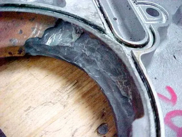
- Pump casings and impellers. The photo above shows a cast pump casing cut away along the flow path.
- Pitted surfaces. AMPP notes that pitting on the inside of a tube adds turbulence that can raise erosion rates quickly and end in a leak. The two mechanisms feed each other, as covered in our guide to pitting corrosion in oilfield tubing.
- Cut ends and poor fit-up. AMPP lists burrs left on cut tube ends and misaligned welded or flanged joints as sources of local turbulence.
The API RP 14E erosional velocity, explained
API RP 14E gives the equation most operators know:
Ve = c / √ρm
Ve is the erosional velocity in ft/s, and ρm is the gas/liquid mixture density at flowing pressure and temperature in lb/ft³. According to the Wear review, RP 14E says “for solid-free fluids values of c = 100 for continuous service and c = 125 for intermittent service are conservative.” For solid-free fluids where corrosion isn’t expected, or is controlled by inhibition or corrosion-resistant alloys, it allows c-factors of 150 to 200 for continuous service and up to 250 for intermittent service.
A worked example, as plain arithmetic: a line with a mixture density of 4 lb/ft³ in continuous service at c = 100 gets Ve = 100 / 2 = 50 ft/s.
The same review lists what the equation leaves out:
- It was written for new piping on offshore production platforms, not onshore leases or downhole tubing.
- It treats flowlines, manifolds and headers the same and doesn’t single out chokes, elbows or tees, where most of the damage happens.
- It says velocity can go up as density goes down. Sand erosion and droplet tests show the opposite: erosion is higher in low-density fluids.
- It gives no erosion rate, above or below the limit.
- For solids, RP 14E only says “fluid velocities should be significantly reduced.” It gives no numbers. The review calls this the equation’s most significant limitation, because some sand and some corrosion are almost always present in real production.
- Even “sand-free” service with sand rates as low as a few lb/day can see very severe damage at high velocities.
The review lists alternatives that deal with sand directly, including the Salama model, the DNV GL model and the Tulsa model. One more RP 14E point is worth knowing for liquid lines: velocity shouldn’t drop below 3 ft/s, to keep sand from settling out. Settled sand causes its own problem, under-deposit corrosion. So the right velocity is high enough to carry sand and low enough not to cut the steel.
Erosion corrosion detection: what to look for and how to inspect
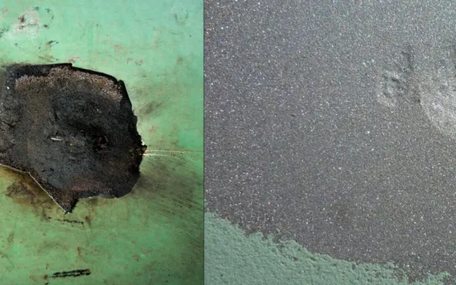
Armoloy’s page lists the visual signs: grooves that line up with the flow, local thinning near bends, and roughened surfaces. On pulled tubing and opened fittings that usually means smooth, scooped-out metal with little corrosion product in it, unlike the crusty look of pitting in still water.
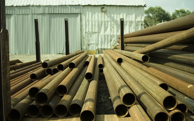
Visual checks only cover what you can see. For tubing, SPE’s PetroWiki lists “mechanical wear and erosion” among the typical defects field inspection looks for, along with inside and outside pits. It covers the methods:
| Method | What it covers | Limit |
|---|---|---|
| Electromagnetic (EMI, flux leakage) | Pits, wall loss and other defects along the pipe body | PetroWiki says it typically won’t find defects in the upset or threaded area |
| Ultrasonic | Wall thickness and flaws in the pipe body | Only where the probe or scan covers |
| Calipers | Internal wall loss while tubing is in the well | Damaged joints still have to be pulled |
| Magnetic particle and thread gauges | Upsets, ends and threads | Outside surface only |
The upset-and-thread gap matters for erosion because the North Sea failure in the review happened at a flow coupling. A full-length body scan should be paired with a connection check.
For surface piping, on a lease with an SPCC plan, 40 CFR 112.9(d)(4) requires a maintenance program for flowlines and intra-facility gathering lines. It also requires inspection or testing on a regular schedule “for leaks, oil discharges, corrosion, or other conditions that could lead to a discharge.” A thinned elbow downstream of a choke is that kind of condition.
How to control erosion corrosion
AMPP’s prevention list, applied to a lease:
- Slow the flow where you can. Larger line sizes lower velocity.
- Cut down on abrupt direction changes and flow restrictions. Every turn is a wear point.
- Put sacrificial metal where the hits land. AMPP suggests replaceable impingement plates or baffles and extra wall thickness in vulnerable areas.
- Get the solids out. Filtration or settling, which on a lease means a desander or sand trap ahead of the equipment you want to save.
- Deal with the corrosion half too. De-aeration, inhibitors, cathodic protection and coatings all appear on AMPP’s list.
- Clean up fit-up. Deburr cut ends and line up welded and flanged sections.
- Inspect the wear points on a schedule. The worst spots are predictable, so check them first and keep the readings so you can see the trend.
When a thinned elbow or joint fails under pressure, the line can whip. Engineered restraints on high-pressure iron keep a failed section in place while the wall thickness program does its work.
EMI tubing inspection in the Permian Basin
Site Safe Solutions runs EMI inspection on production tubing at the wellhead or on the lease. The non-contact scan finds wall loss, rod wear and corrosion along each joint and produces digital trace records, so worn joints come out of the string and the rest go back to work. The company describes itself as the only provider in the Permian Basin with ACE-Making technology, and it also supplies high-pressure restraint systems for surface iron. If a sandy well keeps eating tubing, send us the size and joint count and we’ll set up a scan on the next pull.