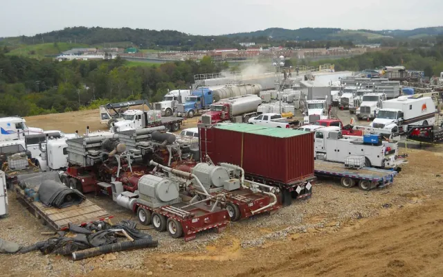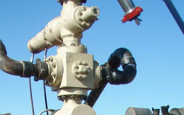
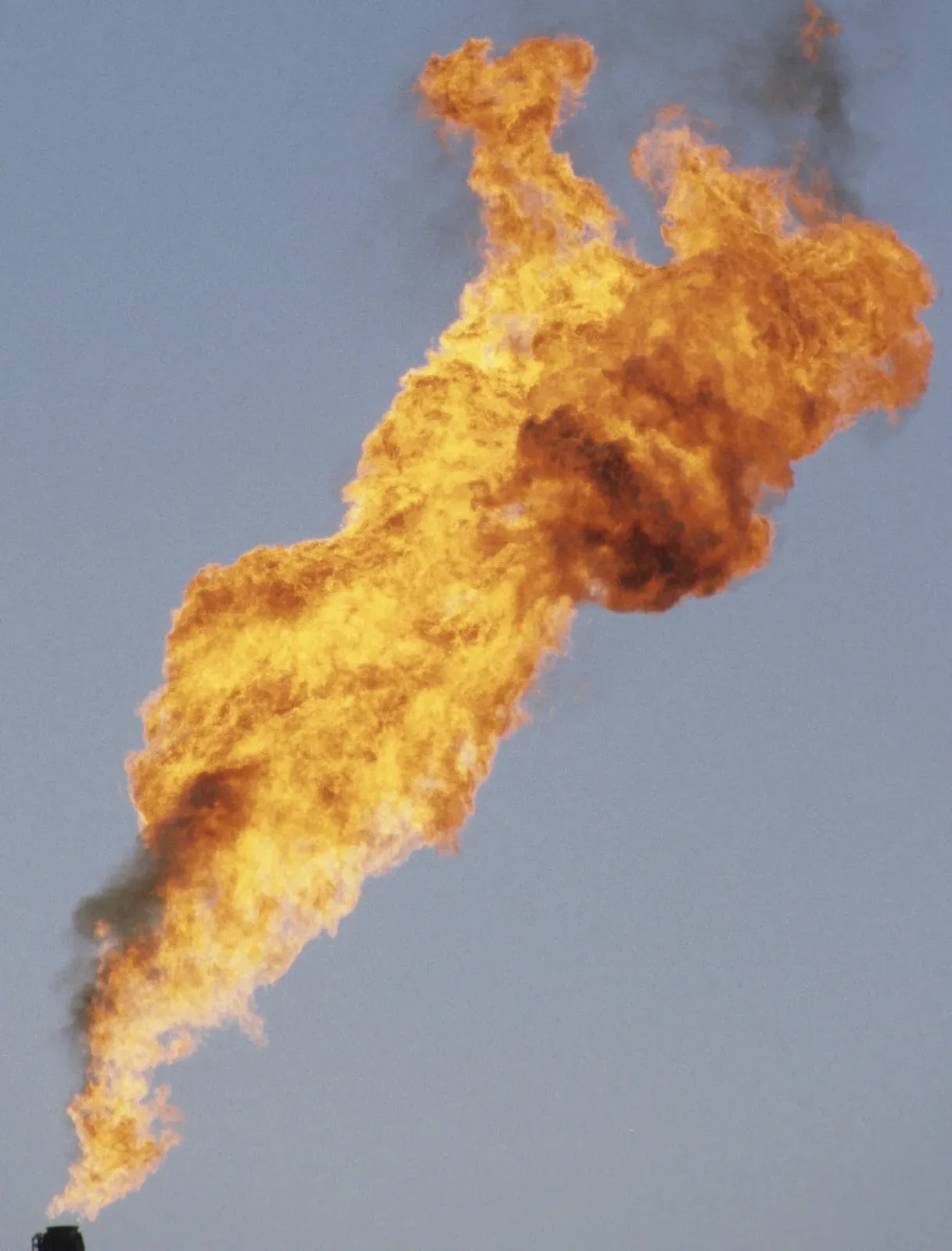
Flowback is the stage after a frac when the well is opened and the treatment fluid comes back to surface, carrying sand, salt water, gas and the first oil. A flowback crew runs it through high-pressure iron, a choke, a sand trap and a separator, then into tanks. For the length of the job, most of the fluid on the location is moving under pressure through temporary equipment. EPA’s review of fracturing-related spills found that flowback and produced water was the fluid spilled most often, and that tanks and pits were the most common source. That’s why flowback needs the same planning as the frac.
What is flowback in oil and gas?
SLB’s Energy Glossary defines flowback as letting fluids flow from the well after a treatment, either to get ready for the next stage or to clean the well up and return it to production. EPA draws the line by timing. The first fluid back after frac pressure is released is called flowback. Fluid that comes up with oil and gas once the well is producing is called produced water.
How much comes back varies widely. EPA’s 2015 spill study, citing earlier work, puts it at 10 to 70 percent of the fluid injected. The same report describes flowback as typically highly saline. It often carries metals and naturally occurring radionuclides, plus organic chemicals from the frac fluid and the formation. On location, treat it as salt water carrying oil, gas and sand.
The flowback spread, piece by piece
Every flowback company lays its equipment out a little differently. The pieces below are common, listed from the wellhead downstream, with the failure each one is known for.
| Component | Its job | What usually goes wrong |
|---|---|---|
| Wellhead and choke manifold | Controls rate and back-pressure on the well | Chokes and seats wash out from sand; pressure surges when a choke is changed |
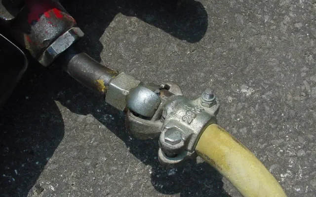
| High-pressure flowback iron | Carries returns from the wellhead to the trap | Erosion at elbows, tees and valves; worn or mismatched unions |
| Sand trap or desander | Drops proppant out before the separator | Plugging; erosion at the inlet; sand dumped onto the pad during clean-out |
| Separator | Splits gas, oil and water | Upsets that carry oil or gas over to the tanks |
| Flowback tanks | Hold returned fluid until it’s hauled or piped away | Overfills; valves left open; gas at open hatches |
| Load-out hoses and pumps | Move fluid to trucks or a transfer line | Leaks at hose connections; drips during hook-up and disconnect |
The iron tends to fail from wear, and that means a pressure release. The tanks tend to fail from handling, and that means a spill. So the iron needs inspection and restraint, and the tanks need containment and someone watching them.
Sand wears out flowback iron
Proppant that comes back with the fluid acts like a sandblaster on the inside of the iron. A 2024 study in Materials looked at surface lines in a shale gas field in China’s Sichuan Basin. It called the erosion caused by proppant flowback “significant.” Lines there perforated at the elbows after five months of service. The pipe from the wellhead to the desanding skid failed after two months, with 3 to 4 mm of wall eroded away. The researchers found the damage concentrated where flow changes direction, at elbows, tees and valves. They tested harder lining materials for those spots.
That field’s rates and pipe aren’t a Permian flowback spread, but the mechanism is the same. In practice that means:
- Every elbow, tee and target on the flowback line is a wear point. Fewer turns means fewer of them.
- Ask the flowback contractor which joints and elbows get thickness checks, and how often during the job.
- API published Std 16FI on January 20, 2026. It covers temporary high-pressure equipment used during hydraulic fracturing, including piping, hoses, connections, manifolds and relief devices. Flowback iron sits downstream of the frac, but it’s still temporary high-pressure iron. Ask whether it’s inspected, tracked and retired with the same discipline.
- An eroded elbow that lets go under pressure behaves like any other failed connection. The line whips, and the people near it are in the line of fire. Our guide to why an unrestrained line whips covers the physics. The answer is an engineered restraint on the iron and hose, anchored so a failed section stays put.
Where flowback spills actually come from
EPA’s 2015 study reviewed 457 spills tied to hydraulic fracturing in nine states, Texas among them, from January 2006 to April 2012.
- Flowback and produced water was the most common fluid spilled: 225 spills, 48 percent of the total by material. It was also about 2 million gallons, 85 percent of all the volume reported. The median spill was 990 gallons.
- Storage units such as tanks and pits were the most common source, at 46 percent of spills.
- Human error caused more spills than anything else. The single most common scenario was flowback or produced water spilled through human error, 19 percent of all spills, with a median of 1,000 gallons.
- Spilled fluid reached soil in 64 percent of cases.
In one of the report’s examples, 8,400 gallons of flowback spilled because a valve on a flowback tank was left open. In another, a tank “overflowed during flowback operations, filled the bermed containment area, ran over the top of the berm and onto the pad.” That one was 4,200 gallons.
So the containment around flowback tanks has to hold what a tank can actually dump. And someone has to own tank levels and valve positions on every shift.
Containment for flowback tanks
Flowback tanks holding oil-bearing fluid are oil containers under EPA’s SPCC rule. The rule covers a facility once its aboveground oil storage passes 1,320 gallons, counting only containers of 55 gallons or more, provided a discharge could reach navigable waters.
Two paragraphs come up on a completion location. Section 112.8(c)(11) covers mobile or portable containers. It asks for containment that holds the largest single container or compartment plus freeboard for rain. Section 112.10(c) covers drilling and workover operations. It asks for catchment basins or diversion structures for fuel, crude oil or oily drilling fluids. Which paragraph governs a given pad is a call for the SPCC Plan and whoever certifies it. The practical layout is much the same either way.
- Size the berm to the biggest tank plus rain. The frac tank containment guide works through the math for a row of tanks.
- The choke manifold, separator and load-out connections drip all job long. Put liner under them as well as under the tanks.
- Haulers come and go around the clock. Drive-over walls or mats at the load-out keep a truck from flattening the berm it’s parked next to.
- Section 112.8(c)(10) says to promptly remove oil that collects in diked areas. A berm half full of rainwater and drips has half the room it was built for.
- Walk the low side of the pad. If a berm fails, you want to know whether the fluid runs to a bar ditch, a draw or a pasture ahead of time.
Gas at the tank hatches
Flowback tanks take in fluid that’s still giving off gas. A 2016 report in CDC’s MMWR involved NIOSH and OSHA staff. They reviewed fatality reports from January 2010 through March 2015 and found nine oil and gas extraction workers who died after opening the hatches of hydrocarbon storage tanks. The suspected causes were inhalation of hydrocarbon gases and vapors and oxygen-deficient air. The authors proposed controls that reduce or remove workers’ exposure. On a flowback location that means remote level readings where the tanks have them. Where a hatch has to be opened, the company’s gas-monitoring and entry rules apply.
Pre-flowback walkdown
Run through this before the well is opened, and again after any rig-up change.
- Flowback iron and hoses are restrained and anchored along their full run, including where they cross walkways and the load-out lane.
- The contractor has named the elbows and tees that get wall-thickness checks, and how often.
- Unions are matched by figure number and pressure rating.
- The tank berm holds the largest tank plus freeboard. The liner has no holes, and drain valves are closed.
- Liner or mats sit under the choke manifold, separator, sand trap clean-out point and load-out hoses.
- Every tank valve is tagged, and one named person owns tank levels each shift.
- The hatch and gauging procedure is agreed, with gas monitors on location.
- Spill kits are staged, and the vac truck contact is posted.
- The drainage path off the pad is known, and nothing low-side is unprotected.
Cleaning up after the job
When flowback ends, the iron, mats and liners come off the pad coated in sand, oily residue and salt. Wash them on containment so the wash water is caught rather than run onto the lease. Site Safe Solutions’ equipment cleaning crews pressure-wash mats, trailers, tanks and rigs, and that’s a good time to look over mats and liners before they go to the next job.
Restraints and containment for completion work
Site Safe Solutions supplies high-pressure restraint systems for hose and iron lines, containment systems with HDPE liners, and drive-over Fast Mats for oilfield sites in the Permian Basin. If a completion is coming up, send us the pad layout and the tank count and we’ll plan the restraints and containment around the flowback spread.