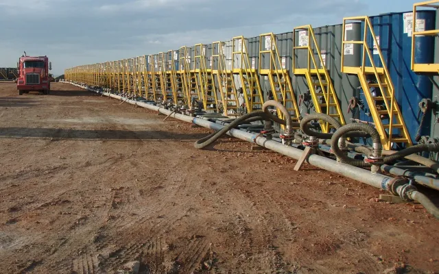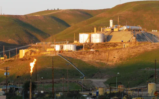
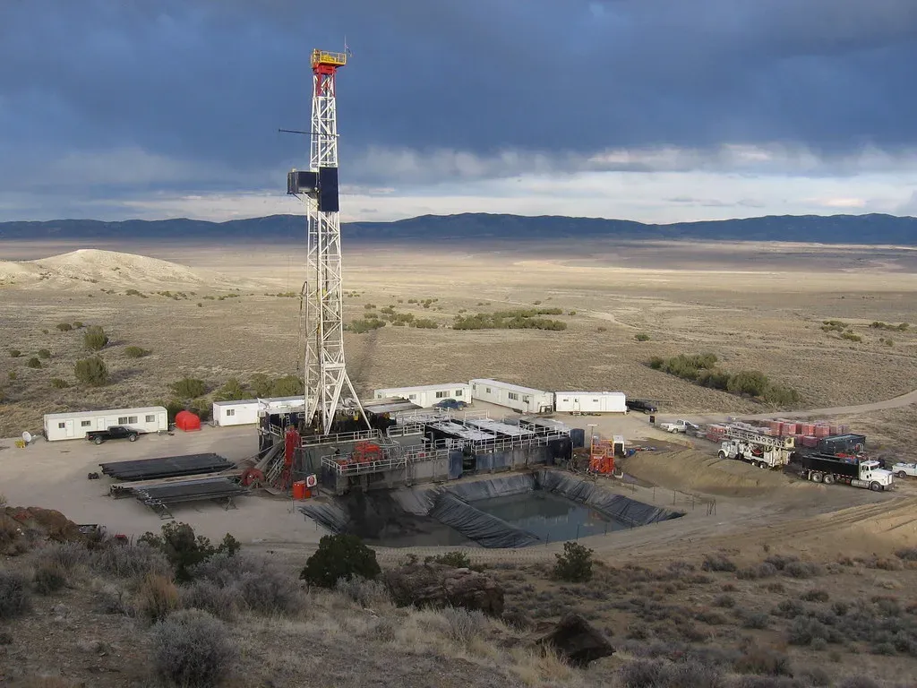
A well pad is the graded, compacted patch of ground that holds the drilling rig while a well is drilled and the wellhead and production equipment once it produces. On modern horizontal development one pad often carries several wells. The pad stays in use for decades, and what sits on it changes several times. A rig and its fuel come first, then a frac spread and flowback tanks, then a tank battery, with workover rigs in between. Each stage brings its own spill risks and its own section of the federal SPCC rule, so containment has to change with the pad.
What is a well pad?
Definitions vary a little by regulator. Durango, Colorado’s land use code defines a well pad as the area where permanent operations for oil and gas production take place. It must include at least the land inside the drilling rig anchors, and it can hold one or more wellheads and related equipment.
The U.S. Energy Information Administration describes a drilling pad as a location that houses the wellheads for a number of horizontally drilled wells, often five to ten. Rigs fitted with hydraulic walking or skidding systems can move a few yards to the next wellhead without rigging down. EIA linked that change to faster drilling. In its example, Eagle Ford operators averaged about 19 days per horizontal well in June 2012, down from 23 days in 2011. EIA also notes that clustering wells on one pad shrinks the surface footprint.
How a well pad is built
The Bureau of Land Management’s Gold Book sets surface operating standards for oil and gas work on federal lands. Its construction guidance covers points that apply to most pads:
- Topsoil is stripped from the whole cut and fill area and stockpiled separately for reclamation later.
- Fill is compacted to reduce the chance of settling or slope failure.
- The area under the rig substructure must be level and able to support the rig.
- The drill rig, tanks, heater-treater and other production equipment must not sit on uncompacted fill.
- The area for mud tanks, generators and fuel tanks should have a slight slope or ditching so the work area drains to the pit.
- Ditches, berms or waterbars above cut slopes can divert storm water away from the location.
Two of those points matter later for containment. Tanks and equipment on soft fill can settle under load. The way the pad drains decides where a spill runs before anyone sees it. On private land in Texas, state rules and the operator’s own standards apply instead of the Gold Book, but the engineering is the same.
The life of a pad, stage by stage
| Stage | What’s on the pad | Common spill sources | SPCC section |
|---|---|---|---|
| Drilling | Rig, mud system, fuel tanks, generators, pipe racks, reserve pit or closed-loop system | Fuel transfers, mud and cuttings, drips from pipe | 40 CFR 112.10 |
| Completion and flowback | Frac spread, water tanks, flowback iron, sand trap, separator, flowback tanks | Tank overfills, hose connections, flowback fluid | As classified in the site’s SPCC plan; 112.7 general rules apply |
| Production | Wellheads, separator, heater-treater, oil and produced water tanks, load line | Tank and valve leaks, truck loading, flowlines | 40 CFR 112.9 |
| Workover | Workover rig, pump truck, tanks, pipe racks | Wet rods and tubing, transfer hoses | 40 CFR 112.10 |
| Interim reclamation | Wellhead and production equipment on a smaller pad | Same as production, in a tighter space | 40 CFR 112.9 |
Under 112.10, a drilling or workover operation has to position its equipment to prevent a discharge and provide catchment basins or diversion structures for fuel, crude oil and oily drilling fluids. It also needs a blowout prevention assembly before drilling below any casing string or during workover operations. Our articles on flowback and workover rigs cover those stages in detail.
Reserve pits and liners
Where a reserve pit is used, the Gold Book sets out how to build it on federal land. The pit should normally sit entirely in cut material, not in fill. On sloping sites at least 50 percent of it should be below original ground level, to help prevent the pit dike from failing. It should hold all expected muds, cuttings, frac fluids and precipitation with at least 2 feet of freeboard.
For lined pits, the Gold Book calls for liners with a permeability below 10⁻⁷ cm/sec, compatible with everything that goes into the pit. Synthetic liners should be at least 12 mils thick and resistant to UV, weathering, chemicals, punctures and tearing, and some states require thicker liners. Sand, clay or felt bedding goes underneath where rock could puncture the liner. The Gold Book also encourages closed-loop drilling systems or lined pits where pits will hold moderate or high levels of hydrocarbons and chloride. Texas pit rules come from the Railroad Commission, so check its current requirements for pads in the state.
Containment once the well produces
When the pad becomes a production site, 40 CFR 112.9 takes over. The core requirement in 112.9(c)(2) is that tank battery, separation and treating installations need secondary containment for the entire capacity of the largest single container, plus enough freeboard to contain precipitation. Drainage from undiked areas has to go to a catchment basin or holding pond. The Gold Book repeats the same sizing for federal leases. It adds that containment dikes must not be built from topsoil or coarse, insufficiently impervious spoil, and that containment is strongly suggested for produced water tanks.
Section 112.9(b) adds two operating rules that are easy to miss:
- Dike drains at tank batteries and treating areas must stay closed and sealed except when draining uncontaminated rainwater. You inspect the diked area before draining, and any oil on the water is removed and returned to storage or disposed of properly.
- Field drainage systems, such as drainage ditches, road ditches, oil traps, sumps and skimmers, must be inspected on a regular schedule for oil from small discharges, and any oil removed promptly.
Whether the pad needs an SPCC plan at all depends on its aggregate aboveground oil storage. Under 40 CFR 112.1, a facility with 1,320 U.S. gallons or less is exempt, counting only containers of 55 gallons or more. Our tank battery article walks through where batteries leak.
Interim reclamation shrinks the pad
Once a well is producing, the Gold Book calls for interim reclamation of every part of the site not needed for production. Those areas are recontoured, topsoil is respread and the ground is revegetated, often to within a few feet of the production equipment. It also says to leave enough level area to set up a workover rig and park equipment.
That has two effects on containment. Equipment that sat on a wide pad during drilling now sits on a tighter one, so berms and walls have less room and traffic runs closer to them. And the workover rig will come back to that smaller pad. Modular or drive-over containment that can be set up for the job and taken down afterward suits a pad that keeps changing shape.
Pad walk checklist
- Which stage the pad is in, and which SPCC section applies to it now
- Which way the pad drains, and where a spill from each tank would run
- Containment sized for the largest single container plus rain freeboard
- Dike drain valves closed and sealed, with drainage records kept
- No tanks or equipment sitting on soft or settled fill
- Mats or liners under transfer points, hose connections and the load line
- Field ditches, sumps and traps checked for oil
- Room left for a workover rig, and a containment plan for when it arrives
Containment for every stage of the pad
Site Safe Solutions designs and installs containment systems for well pads and production sites in the Permian Basin, from modular drive-over containment to primary pads and high-wall systems with HDPE liners. We also supply Fast Mats for drive-over spill protection at load lines and transfer points. Tell us where the pad is, what’s on it and what’s coming next, and we’ll lay out containment that fits it.