A plug valve is a quarter-turn valve: a cylindrical or tapered plug with a hole through it sits in the valve body, and a 90-degree turn lines the hole up with the pipe or blocks it. The same word covers a brass gas cock on a house line, a 450 psi sewage valve and the 15,000 psi valves on frac iron. On an oilfield location the plug valve is a common shutoff in temporary high-pressure lines. Four things decide whether it’s safe there: its rating, its condition, which way it’s turned and what the line does if something lets go.
What is a plug valve?
Wikipedia’s definition covers the basics. Plug valves have “cylindrical or conically tapered” plugs that rotate inside the body, with one or more passages running sideways through the plug so fluid can flow when the valve is open. The common version has two ports and two positions. Because the ports sit at opposite ends of the body, a quarter turn takes it from open to shut. Most have a stop that limits the handle to that quarter turn.
The entry calls the design simple and often economical. Plug valves usually have no bonnet, and the far end of the plug is often exposed and held in the body by a retaining mechanism. On a pressurized line, that hardware is what keeps the plug in the body.
Types of plug valves
Valve suppliers sort plug valves by how the plug seals against the body. Norgas Controls, a gas equipment distributor, lists four types, and Wikipedia and DeZURIK add the multi-port versions.
| Type | How it works | Where you see it |
|---|---|---|
| Lubricated | Sealant between plug and body does part of the sealing | Dirty upstream service. Norgas says these handle abrasive or corrosive material without clogging but need frequent resealing |
| Non-lubricated | Elastomer sleeve, lift-type plug or full lining in place of grease | Low-maintenance process service |
| Eccentric | Off-center plug gives a higher seating force with less friction through the stroke | Sewage, sludge, slurries and air |
| Expanding | Several parts move so the seals don’t drag while the plug turns | Service where seal wear or product contamination is the concern |
| 3-way and 4-way | Extra ports let one valve divert or combine flow | Diverting and switching service |
Wikipedia adds one maintenance point about lubricated valves. If the plug has sat in one position for a long time, lubricant can be added through the greaser with the valve in service.
What a plug valve is rated for depends on who built it for what
Search results for “plug valve” mix water-plant, pipeline and well-service products as if they were one thing. Their ratings are far apart.
| Service | Example rating | Source |
|---|---|---|
| Water and wastewater eccentric plug valves | 175 psi CWP in cast iron, 285 psi in ductile iron, up to 450 psi in special designs | DeZURIK product data |
| Pipeline valves under API Spec 6D | ASME Class 150 through Class 2500 | API Spec 6D, 25th edition |
| Well-service plug valves on flow iron | Up to 15,000 psi working pressure, 2 in. and 3 in. sizes | SLB flow iron data |
API Spec 6D covers “axial, ball, check, gate, and plug valves for application in the petroleum and natural gas industries,” and its data sheets list pressure classes from 150 to 2500. Wikipedia also lists API Std 599, Metal Plug Valves, as a reference standard. Neither rating scheme matches the working-pressure numbers stamped on treating iron. Read the body markings and the paperwork before it goes in a line.
Plug valve vs ball valve vs gate valve
All three are shutoff valves. They differ in what moves inside.
| Plug valve | Ball valve | Gate valve | |
|---|---|---|---|
| Closing element | Cylindrical or tapered plug with a port through it | Sphere with a bore through the middle | A gate lifted out of the flow path |
| Operation | Quarter turn | Quarter turn; handle lies in line with flow when open | Lifting the gate |
| Flow when open | The port in a tapered plug is usually reduced (Norgas) | Flows through the bore | Hardly restricts flow when fully open |
| Known weak points | Higher friction, so more force to turn; possible galling; poor for throttling (Norgas) | Traps fluid in the center cavity when closed, which can crack the body in a freeze | Not a quarter-turn valve, so the handle doesn’t show position at a glance |
Wikipedia puts ball valve designs at up to 15,000 psi as well, so pressure alone doesn’t decide the choice.
Plug valves on frac iron and flowback lines
SLB’s flow iron data describes the well-service plug valve. It’s offered in 2 in. and 3 in. sizes at up to 15,000 psi working pressure, with 1502 hammer wing unions or clamp-style hub connections on the ends. The listed uses run “from high-stage-count hydraulic fracturing to cementing, well testing, and even abrasive flowback.” Sour gas versions are available, and the valves can be fitted with bar caps, gear operators or hydraulic actuators.
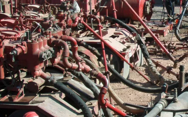
So on location you’ll find plug valves in the treating lines between the pumps and the wellhead and in flowback lines. A high stage count means a lot of open-and-close cycles, and flowback is abrasive.
The hammer union ends bring a known hazard with them. A 1502 valve can be made up to a look-alike union of a lower figure number, which is the failure our hammer union mismatch guide describes. The valve is also part of the temporary high-pressure system that API Std 16FI, Frac Iron Guidelines and Requirements, was written for. API published the first edition in January 2026, and its release names piping, hoses, connections, manifolds and pressure-relief devices. It doesn’t call out valves by name, so ask your iron provider how their valves are inspected and tracked under their program. The frac iron safety guide covers the standard. For sour wells, see NACE MR0175 before accepting a standard-service valve.
How plug valves get people hurt
The valve is seldom the only cause. The usual story is a valve in the wrong position, the wrong valve for the pressure, or a worn one.
IADC Safety Alert 04-31 shows how fast it happens. A crew was filling casing through a mud line fitted with a low-pressure valve. When the casing was full, the floorman closed the valve. Pressure built past the valve’s working pressure, it failed, and he was hit by debris. It was a lost-time injury. The alert doesn’t say what type of valve it was, and it wouldn’t matter. Closing any valve against a running pump puts the pump’s pressure on the weakest part in the line.
OSHA’s hydraulic fracturing and flowback guide (OSHA 3763) builds its pressure controls around the same idea. Its list for pressure pumping includes:
- Set pressure relief devices to discharge at or below the rated working pressure of the weakest component in the system.
- Pressure test the pump and discharge lines to at least the maximum expected treating pressure, without exceeding the rating of the lowest-rated component.
- Walk down the equipment against the written procedure and, whenever possible, verify valve positions and relief settings before starting.
- Don’t let anyone strike a pressurized line or its connections, and confirm lines aren’t pressurized before tightening or loosening hammer unions. OSHA adds that “serious injuries and fatalities have resulted.”
- Inspect equipment at rig-down, document its condition and pull suspected defective equipment from service.
For flowback, the same guide says to inspect and test iron before use and to “be aware of possible sand erosion.” A valve left partly open erodes faster. Norgas lists plug valves as unsuitable for throttling. Crane’s manual for its process plug valves says they are “not recommended for throttling use” and ties that to keeping erosion down. OSHA’s guide gives the flow-control job to choke manifolds, which it describes as the means to reduce pressure and flow velocity from the well in a controlled manner. Run the plug valve fully open or fully closed.
The Crane manual has two more warnings that carry over to any hand-operated valve. Don’t exceed the pressure rating at any time, and don’t use pipe wrenches or cheater bars on the operator. It also calls for wall-thickness checks with micrometers or ultrasonic gauges at least once a year, and more often in severe service. A valve that takes a cheater to turn should come out of the line.
Does lockout/tagout apply to a plug valve?
OSHA’s lockout/tagout standard, 29 CFR 1910.147, lists “a line valve” among energy isolating devices. So in a shop, yard or plant covered by that standard, a plug valve can be the isolation point that gets locked. The standard’s scope, though, excludes “oil and gas well drilling and servicing” at 1910.147(a)(1)(ii)(E).
Well sites still need isolation. OSHA 3763 says an operating plan for pressure pumping should include “energy isolation” along with operating limits and startup and shutdown procedures. On a pumping job that comes down to a written line-up, one person who owns valve positions, and positive confirmation that a line isn’t pressurized before anyone breaks a connection.
Pre-job checks for plug valves
Before pressure-up:
- Read the working pressure and service markings on each valve, and compare them with the maximum expected treating pressure and the lowest-rated component in the line.
- Check the union figure number on both ends against the iron it’s mating to.
- Ask for the valve’s inspection record. If nobody can produce one, don’t run it.
- Cycle each valve fully open and fully closed by hand. Pull any valve that won’t turn by hand.
- Confirm valve positions against the written line-up, including bleed-off and relief lines.
- Check that the lines on both sides of each valve are restrained and that the exclusion zone is marked.
- At rig-down, tag out any valve that leaked, stuck or showed washout.
Restraining the lines a plug valve sits in
A closed valve dead-ends a line, and anything that fails upstream of it has full pressure behind it. OSHA 3763 tells employers to “restrain or secure high pressure lines including relief lines with proven restraint devices and methods” so the lines can’t whip if one fails, and it notes that unrestrained lines “have been known to swing freely, striking workers and equipment.” Every valve adds two more unions to the line, and each union is a place it can part. The line whip hazard guide explains the forces involved.
Restraint systems from Site Safe Solutions
Site Safe Solutions supplies high-pressure restraint systems for oilfield lines in the Permian Basin: hose restraint systems and custom high-pressure iron line restraints for slick-water, nitrogen, energized fluid and standard pumping work. The restraints use a clevis connection at each joint, rig up and down without tools and are installed by certified technicians. A restraint won’t fix a worn valve or a wrong line-up. It keeps the iron close to where it was if one of them causes a failure. To talk through a rig-up, send us the working pressure, the line layout and where the valves and manifolds sit.